
A junction is more than asphalt
Sidewalks, verges and medians are now part of the road cross section. Making them meet at a junction meant matching different slot lists, tapering missing pieces, and knowing when a strip should stop.
A junction is more than asphalt
Part fourteen. The previous article followed a car between two driving lanes. This one goes back to the pieces beside them.
The five junctions in the test map are all four-way crossings. Most of their roads contain the same six slots: sidewalk, verge, two driving lanes, verge, sidewalk. What changes is which arms carry which arrangement. The last one drops the verges and puts a median between the driving lanes.
From high above, they look like variations on one ordinary crossroads. For the road builder, they ask a much less ordinary question: what exactly turns the corner?
A sidewalk is road data
The early road styling proof treated the outside of a road as a boundary. Follow that boundary with a spline mesh and it can make a kerb, a fence or a line of props. That is useful, but a sidewalk is wider than a boundary. It has an inside edge, an outside edge, a material and a place in the cross section.
A sidewalk is now a road slot. So is a verge, parking strip, shoulder or median. The road cross section is an ordered list of those slots, and a style rule in Unreal decides what each kind looks like.
On a straight road, this is simple. Rust sends the two edges of each strip. Unreal sweeps the chosen profile mesh between them. A sidewalk mesh fills the sidewalk slot. A grass material fills the verge. The driving slots get asphalt.
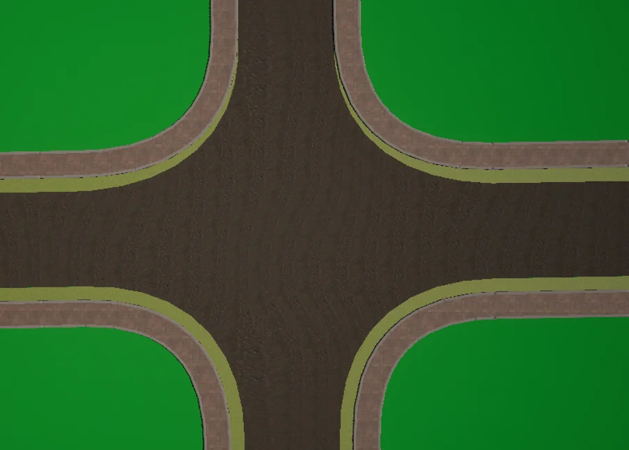
The simple case. Every arm carries the same outer slots, so sidewalks meet sidewalks and verges meet verges.
This is better than generating a sidewalk from the road's outer boundary because it keeps the sidewalk in the same data model as everything beside it. It can change width, appear halfway along a road or be replaced by another kind without inventing a second authoring system.
Then the road reaches a junction and the ordered list on one arm meets a different ordered list on the next.
Pairing strips around a corner
Take one corner between two road arms. Start at the outside and walk inward. If both arms begin with a sidewalk, those sidewalks can share the corner. If both have a verge behind it, the verges can share the next strip.
The first implementation did almost exactly that. It paired the first slot with the first, the second with the second, and stopped when the kinds differed.
That last part was wrong.
Suppose one arm has sidewalk, kerb, verge, driving lane. The next has sidewalk, verge, driving lane. The sidewalks match. The kerb and verge do not, so the walk stops. The valid verge and driving matches behind that extra kerb are never reached.
The current matcher looks ahead instead. When two kinds differ, it checks whether either kind appears later on the other arm. That tells it which list has the extra item. The unmatched strip is handled on its own, then matching continues further inward.
This is closer to aligning two short sequences than joining two road edges. Position alone is not enough. The kind of each slot matters.
A strip can end on the corner
Matching the common slots leaves the extra one. It still needs geometry.
The junction strip can now have a slot at only one end. Its full width starts on the arm that owns it. At the other end, both of its edges meet at the same point, so the strip narrows to zero as it follows the corner.
That is how a verge or sidewalk can end without cutting off every strip behind it.
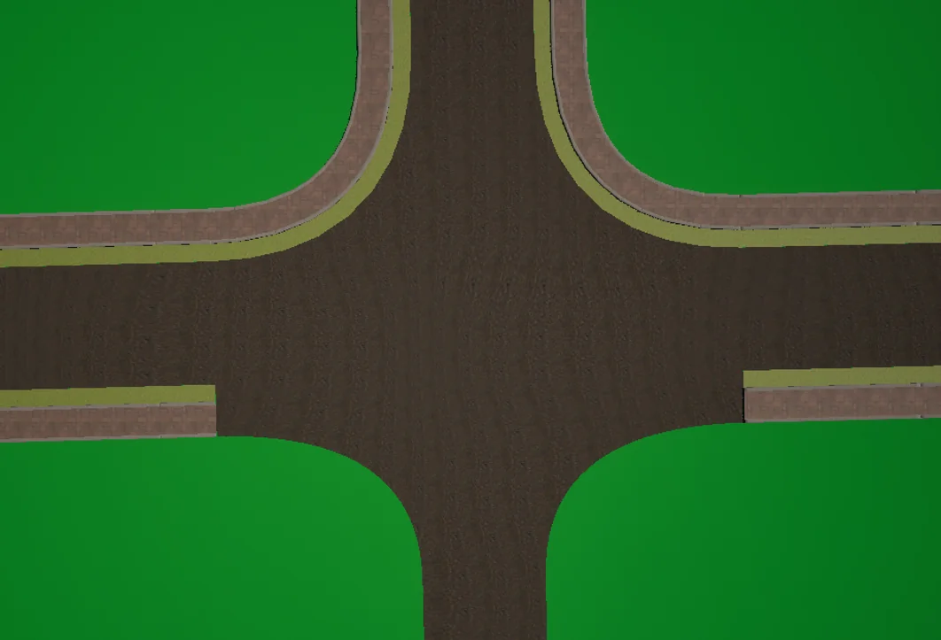
The upper corners carry sidewalk and verge around the turn. On the lower approaches, the unmatched outer strips end at the mouth.
The geometry is built from two offsets of the same rounded junction corner. Each offset starts at the inset for its slot on one arm and ends at the inset on the other. When a slot is missing, the inner and outer inset become equal at that end. The same sampler handles a full-width strip, a strip changing width and a strip tapering to nothing.
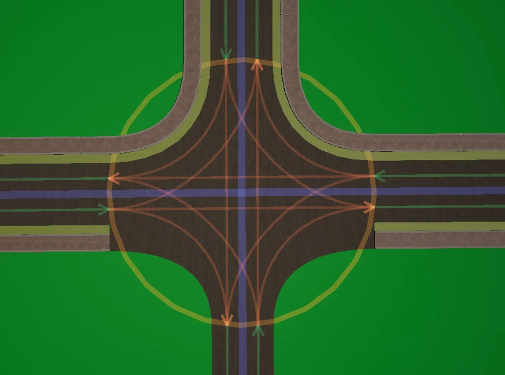
The driving graph crosses the centre of the junction. Sidewalks and verges are separate strips around its edge, even though they all come from the same road cross sections.
This separation matters. Driving connectors answer where a car can travel. A sidewalk corner answers how one non-driving slot meets another. Deriving one from the other would lose the information that one arm has a verge and another does not.
Some strips should stop
Tapering is not always the wanted answer.
A median between opposing lanes should usually stop at the mouth of an ordinary junction. Carrying it around the outside corner would turn a centre divider into a border. Other art may have the same rule: a barrier, a platform edge or a special shoulder might belong along the road but not through the junction.
Each road slot can now mark its style to be cut at the junction. The slot still exists in the authored cross section. Its width and meaning still reach the road end. The styling matcher simply does not offer that terminal slot to the corner builder.
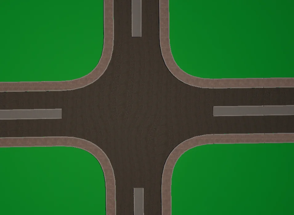
The sidewalks turn around the outside. The medians stop at the four road mouths.
This flag belongs to the slot rather than the material. The author is describing where that part of the cross section exists. Unreal remains free to choose the concrete, plants, barrier mesh or anything else used to draw it.
Fitting the mesh to both edges
Producing the correct strip curves does not guarantee that a mesh will fill them.
Unreal's usual spline mesh deformation follows a centre spline and scales a source mesh across it. That works when the strip has a constant width and both edges bend symmetrically. A junction corner can widen, narrow or taper to zero. Its inside and outside edges travel different shapes.
The DrivEngine surface node now has an option to fit the full profile mesh to the exact strip boundaries. For every source vertex, it works out how far the vertex sits across the original profile. It then places that point between the sampled left and right edges of the strip. The height of the source mesh is kept, so a raised sidewalk stays raised.
This is why the sidewalk and verge in the screenshots follow their own corner widths instead of merely sitting near a centre curve. The same option works on changing road profiles away from junctions.
It is optional because not every mesh wants this treatment. A lamp post or a barrier segment may need to keep its own width. A surface meant to fill a slot should use the boundaries.
The centre line was moving too
The visible corner work exposed two smaller centring mistakes in the road data.
A profile key can add a lane or widen a strip on one side of a road. Its pivot says which seam should stay still while the cross section changes. Before that pivot existed, adding width re-centred the whole road. A new parking lane on the right could move both driving lanes sideways.
Once the whole cross section could move, the lane builder made the opposite mistake. It also used that road alignment inside each individual lane. The lane curve no longer sat in the middle of its own strip. Alignment should move the collection of slots across the road path. It should not move a car away from the centre of its lane.
The lane curve now always uses half of that lane's own width. Junction connectors do the same calculation independently at both ends. That second detail matters when a narrow lane joins a wider one: using the first width at both ends leaves the connector off-centre where it arrives.
These are small arithmetic changes, but they decide whether the driving data sits under the road that Unreal draws.
What the proof shows
The materials in these images are still proof materials. The ground is flat green, the asphalt has no markings, and the median ends are plain blocks. That is fine for this stage. The point of the map is to make the structure easy to inspect.
The five junctions now cover equal outer profiles, missing strips, different arm combinations and a median without verges. Sidewalks are authored as part of the road, not added afterwards by following its boundary. Matching kinds continue around corners. Missing kinds can taper away. Slots such as medians can stop at the mouth on purpose.
There are more art decisions to make, especially how each ending should be capped and how road markings meet the new surfaces. The junction no longer assumes all of its edges contain the same things. That gives the art graph enough information to make those decisions instead of hiding them inside one asphalt shape.
A sidewalk in DrivEngine is now a slot in the road cross section. It sits in the same ordered list as a driving lane, verge, shoulder or median. Unreal can give each kind its own mesh and material.
That works along a road. A junction is harder because four different cross sections meet there. One arm may have a sidewalk and verge. The next may have only a sidewalk. Another may have a median between its driving lanes. The junction has to decide which strips continue around each corner, which taper to nothing and which stop at the road mouth.
The first corner builder paired slots by position. It compared the outer slot of one arm with the outer slot of the next, then moved inward. The first different kind ended the match. One extra kerb or verge could therefore remove every valid strip behind it.
The matcher now looks ahead by kind. Matching sidewalks join. Matching verges join. A strip that exists on only one arm narrows to zero around the corner, while later matches continue. This is why an asymmetric junction can keep its upper sidewalks even when the lower approaches do not carry the same outer strips.
Some slots should never turn the corner. A median should usually stop at the junction mouth. Each road slot can now say that its style ends there, without removing the slot from the road data.
Unreal also gained an option to fit a swept profile mesh to the exact left and right strip boundaries. That keeps the visible sidewalk and verge on the geometry Rust described, even through a changing-width corner.
The screenshots are still from a proof map, with plain materials and no road markings. They now prove the part that mattered: roads with different cross sections can meet without pretending that every junction edge is the same.
This is the short version. The full article has the reasoning, the numbers, and the parts that went wrong.